ContiMech
Robotics & Automation Engineering

Workflow / Capabilities / System engineering process

System engineering · process deck

System engineering process deck

From an operating problem to requirements, architecture, interface contracts, failure behaviour, verification logic, and a package that hardware and software teams can implement without guessing.

Slide 1 of 813%
Slide 01 · Route

System engineering route

Problem → operating scenarios → requirements → system architecture → interface contracts → timing/failure analysis → verification strategy → handover.

InputBusiness goal, existing assets, constraints, risks, standards.
ContractRequirements, architecture, interfaces, expected behaviour.
OutputImplementable specifications and measurable acceptance evidence.
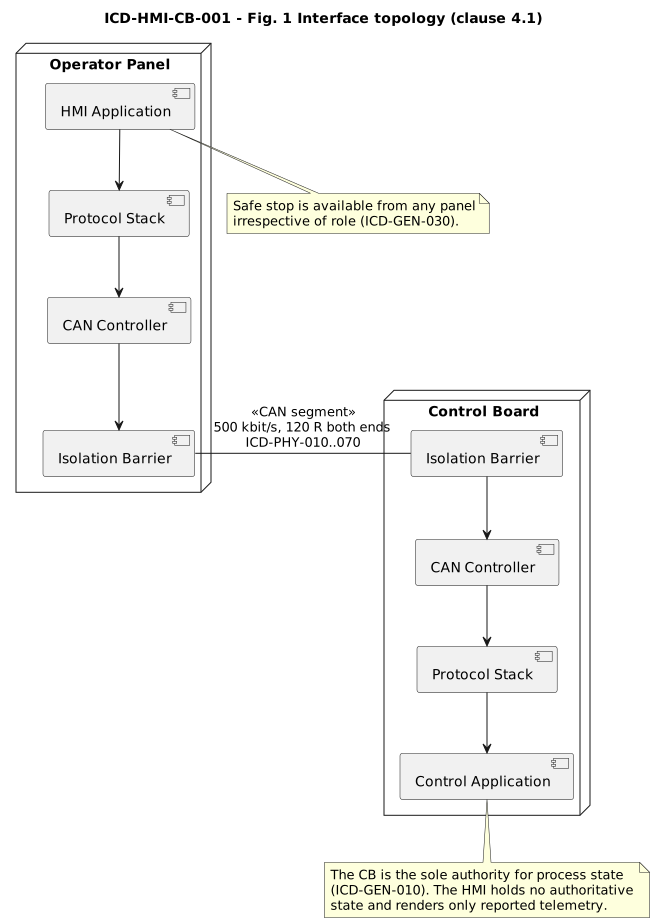
System interface topology between HMI and control board
System viewBoundaries before implementationAuthority, interfaces, physical constraints, and behavioural ownership are made explicit.
Slide 02 · Definition

Problem and operating scenarios

We start from what the system must achieve and how it is actually used, including abnormal conditions.

ActorsOperator, controller, external equipment, service tool, production.
ScenariosStartup, normal operation, configuration, fault, degraded mode, recovery.
ConstraintsTiming, environment, interfaces, safety, security, cost, maintainability.
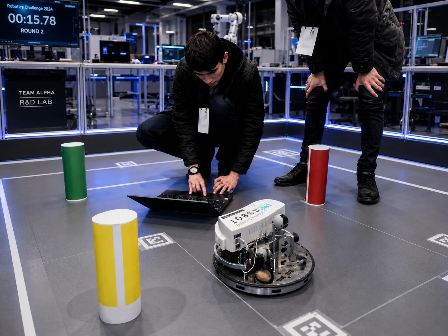
Engineering team validating a robotic system
Gate AUse cases are explicitRequirements are built around observable scenarios, not a disconnected feature list.
Slide 03 · Definition

Requirements and acceptance

Each important behaviour is stated so it can be reviewed and verified.

FunctionalServices, modes, state transitions, roles, configuration rules.
QualityTiming, capacity, robustness, diagnostics, recovery, maintainability.
VerificationTest, inspection, analysis, or design review named with the requirement.
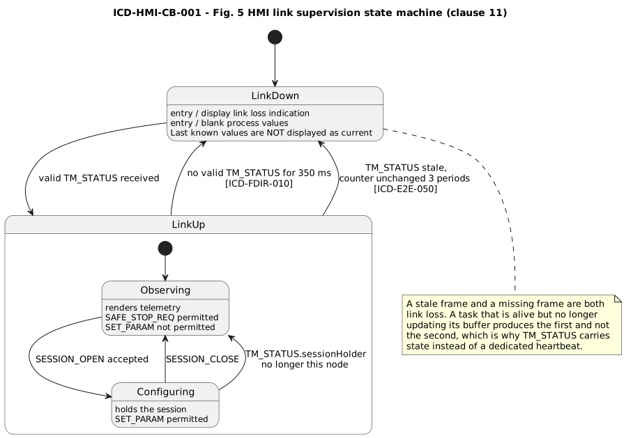
HMI link supervision state machine
BehaviourState is specified, not impliedNormal, lost-link, recovery, and operator-visible behaviour can be traced to requirements.
Slide 04 · Architecture

Architecture, authority, and failure boundaries

We assign ownership of state and decisions before the team starts implementing local logic.

DecompositionComponents, responsibilities, dependencies, data and control flow.
AuthorityWho owns process state, who requests changes, who may reject them.
Failure boundariesWhat happens if a node, link, sensor, actuator, or service disappears.
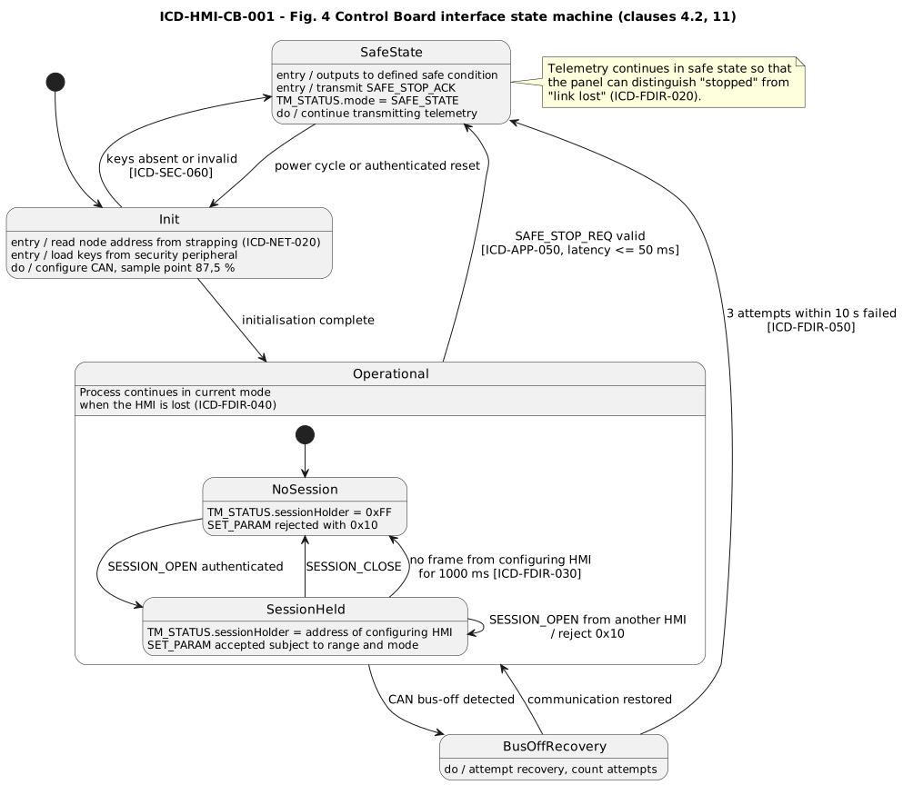
Control board interface state machine
ArchitectureAuthority and safe behaviourState ownership and failure response are part of the system design, not left to integration.
Slide 05 · Interfaces

Interface Control Documents

An ICD is the contract between teams and components. It must be self-standing enough to implement either side without access to the other implementation.

PhysicalMedia, connectors, electrical limits, bit timing, termination, isolation.
LogicalIdentifiers, frame layout, messages, units, ranges, versioning.
BehaviouralSessions, retries, timeouts, fault response, recovery, safe state.
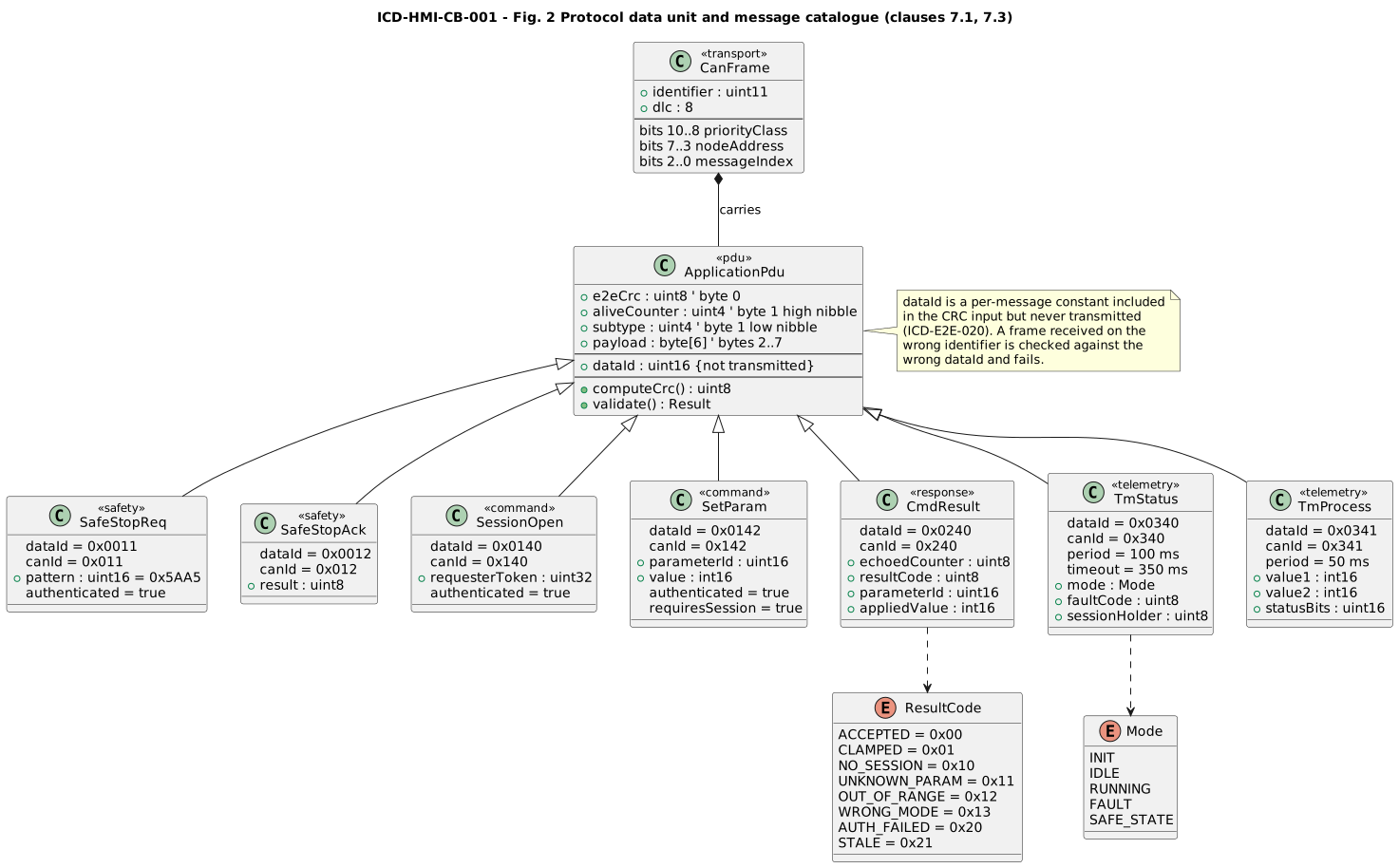
CAN protocol data unit and message catalogue
ICD artifactMessages become reviewable contractsIdentifiers, Data IDs, payload fields, roles, timing, and result semantics are explicit.
Slide 06 · Interfaces

Timing, integrity, security, and FDIR

Communication design includes the failure path, not only the nominal packet.

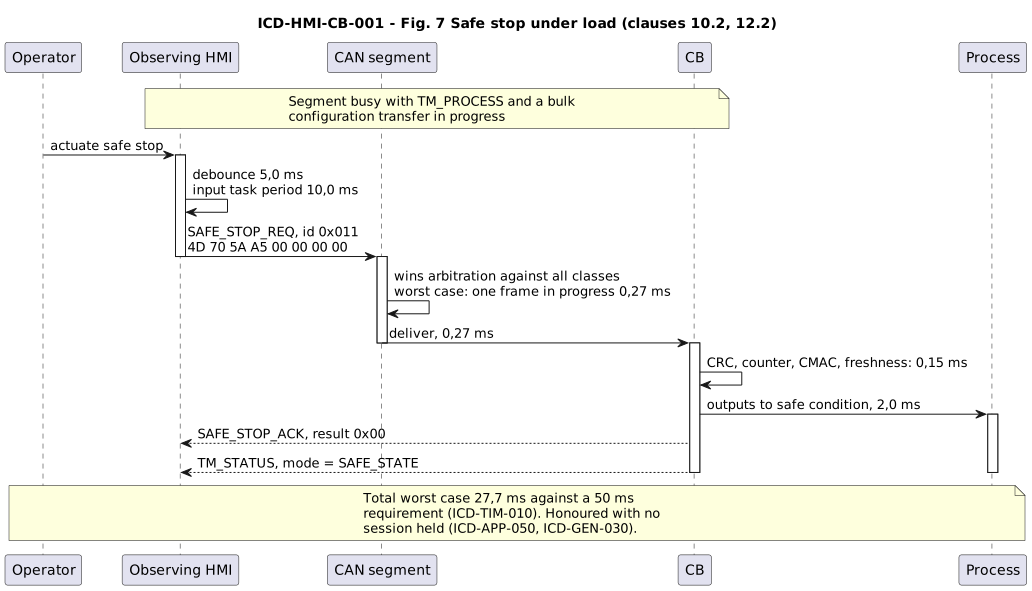
TimingWorst-case budget from input to actuation, bus load, task periods, timeout margin.
ProtectionCRC/E2E, counters, freshness, authentication, replay handling.
FDIRFault detection, isolation, recovery, safe-state rules, diagnostics counters.
Safe stop sequence under bus load
BudgetSafety path is calculated end to endDebounce, tasks, arbitration, transmission, authentication, and actuation belong to one latency budget.
Slide 07 · Verification

Verification strategy before implementation finishes

Tests come from the specification and include the cases that are expensive to discover during final integration.

  • Conformance tests for every message and requirement.
  • Fault injection: corruption, stale buffers, replay, wrong IDs, disconnects, bus-off, brown-out.
  • Load and timing tests concurrent with safety or high-priority paths.
  • Traceability from requirement to design element and verification evidence.
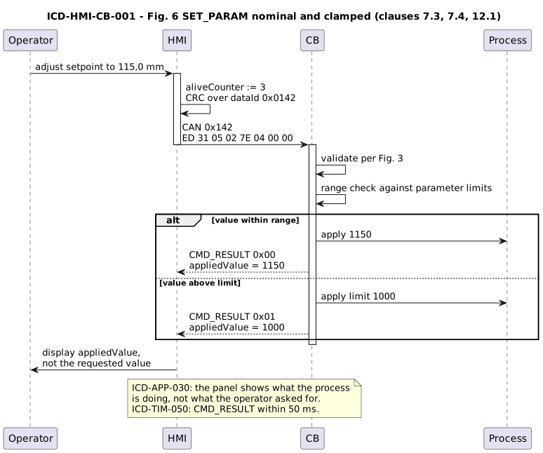
SET_PARAM protocol sequence with accepted and clamped result handling
VerificationNominal and edge-result pathsRequest/response matching, clamping, result codes, and telemetry confirmation can be verified from the contract.
Slide 08 · Reference case

HMI ↔ Control Board CAN protocol

A released public reference ICD demonstrates the documentation standard: unique requirements, verification methods, E2E protection, security, timing budgets, failure management, worked frames, a verification matrix, and a machine-readable catalogue.

InterfaceIsolated classic CAN, 500 kbit/s, priority-correct identifier allocation.
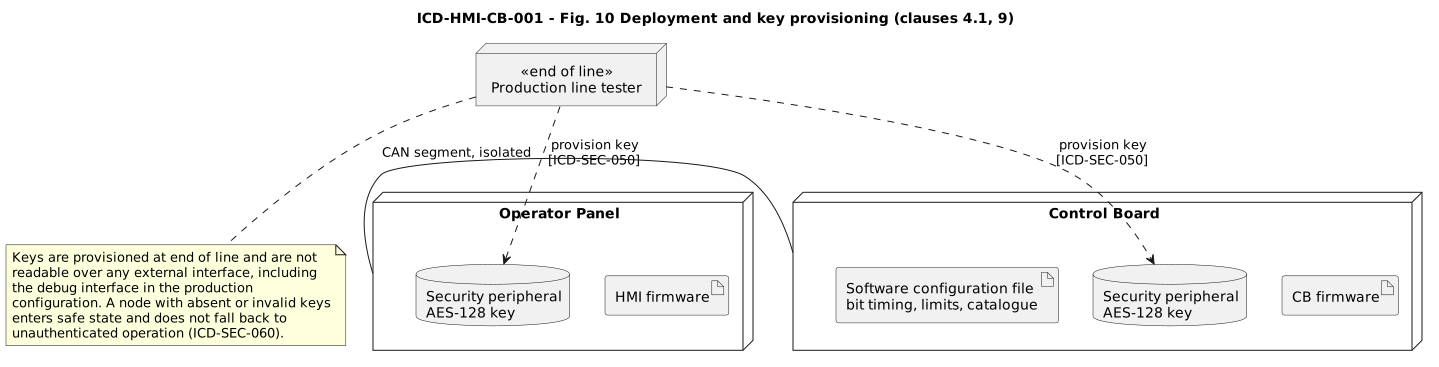
ProtectionData-ID CRC, alive counter, freshness, AES-128 CMAC for state-changing services.
EvidenceWorked frames, safe-stop budget, bus load, FDIR, verification matrix.
Protocol deployment and key provisioning
ReferenceSpecification that closes the implementation gapInterface, security provisioning, configuration, and deployment are treated as one engineering artifact.
System engineering

Need a protocol, ICD, or system contract reviewed?

We can take a focused protocol/ICD work package or own the system interface layer through implementation and verification.

solution@contimech.org