A self-standing communication specification for a distributed industrial control interface: classic CAN, explicit message semantics, E2E protection, authenticated state-changing services, timing budgets, failure management, and verification.
Public referenceCAN · 500 kbit/sE2E + freshnessICD-HMI-CB-001 · Rev 1.0
Publication note. This is a synthetic public reference specification created to demonstrate the documentation and protocol-design standard. It contains no client material; identifiers, addresses, and parameter values are illustrative.
The engineering goal was to make the interface implementable from the document alone. The protocol therefore defines not only bytes and IDs, but authority, session rules, safety priority, timing, E2E checks, security, link-loss behaviour, and how each requirement will be verified.
System contract
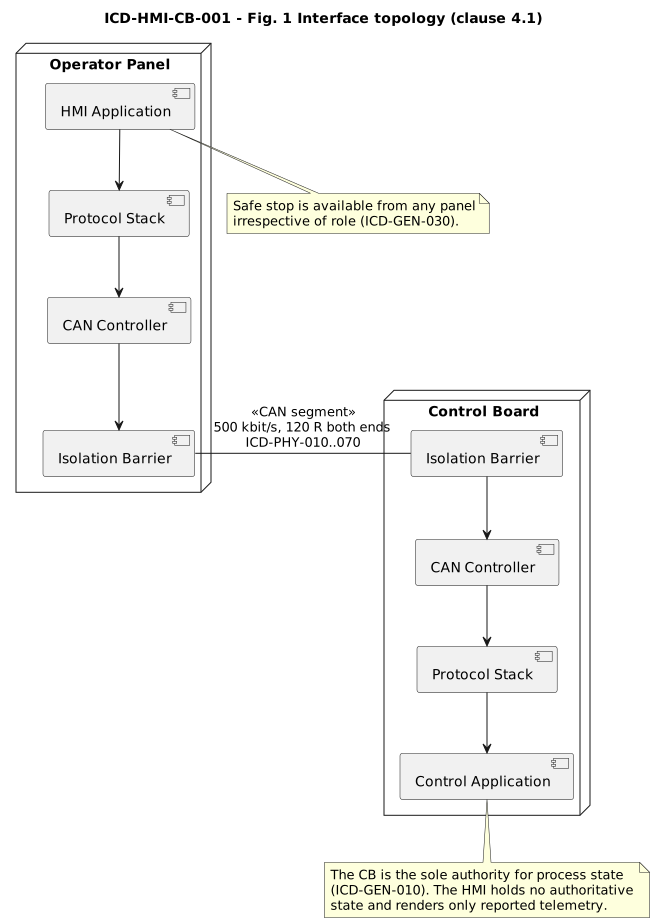
AuthorityThe Control Board owns process state. The HMI requests changes and renders state reported by the CB.
RolesExactly one configuring HMI may change process parameters; observing HMIs may receive telemetry and still issue safe stop.
Safe behaviourLoss of the interface, bus-off recovery failure, invalid security keys, and stale communication have defined behaviours instead of implicit assumptions.
Topology and authority boundary. The interface is a dedicated isolated CAN segment between one HMI and its paired Control Board.
Protocol design choices
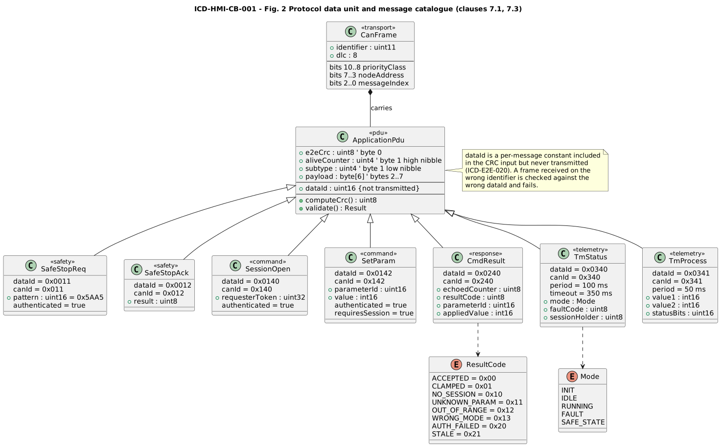
Priority-correct CAN IDsThe 11-bit identifier is partitioned by priority class, node address, and message index so safety traffic wins arbitration and bulk configuration cannot dominate the bus.
Fixed application PDUEvery message uses an 8-byte layout with E2E CRC, alive counter/subtype, and message-specific payload so validation is common and bounded.
Applied-value responsesCommand results echo the request counter and report the value actually applied, including clamping, so the HMI does not display requested state as process state.
Segmented configurationLonger configuration blocks have timeout and sequence rules; partial data is discarded rather than silently applied.
E2E protection and security
Masquerade protectionCRC-8 input includes a per-message Data ID that is not transmitted. A frame delivered on the wrong identifier is checked against the wrong Data ID and fails.
FreshnessA per-message alive counter detects stale cyclic traffic; authenticated services additionally use a monotonic freshness value to reject replay.
AuthenticationSAFE_STOP_REQ, SESSION_OPEN, and SET_PARAM use AES-128 CMAC with a truncated tag; missing/invalid keys do not fall back to open operation.
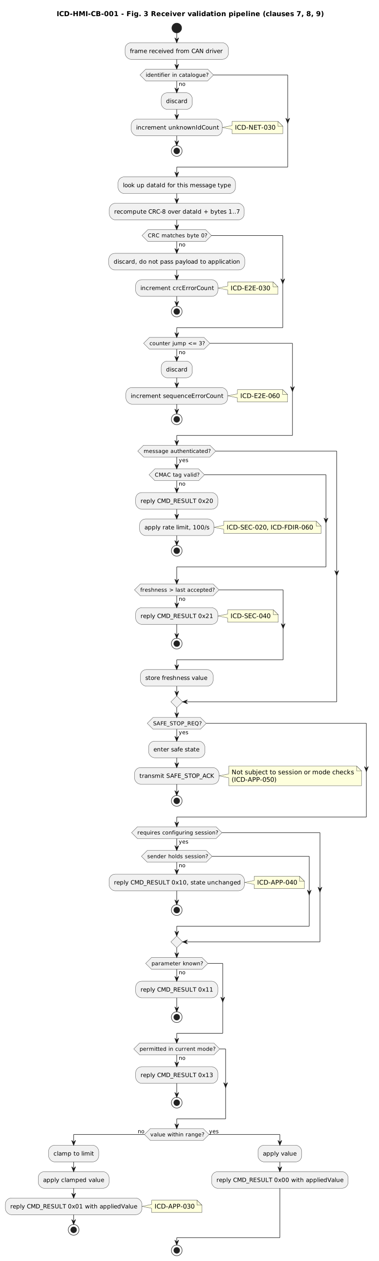
Receiver validation pipeline. Corrupt, stale, replayed, wrong-ID, or unauthenticated traffic is rejected before application state is changed.
Timing is derived, not guessed
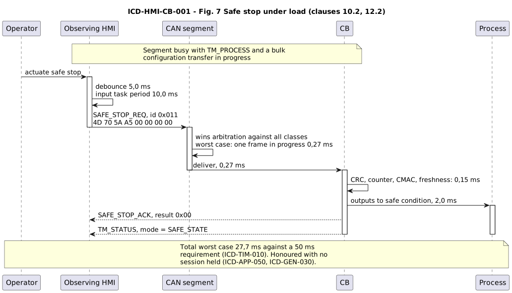
The specification derives the safe-stop path from input debounce, HMI task period, CAN arbitration and transmission, CB receive task, authentication, and output actuation. The calculated worst case is 27.7 ms against a 50 ms requirement. The same document fixes cyclic telemetry periods, response deadlines, and nominal bus load.
Safe stop remains the highest-priority service and is evaluated end to end rather than as a bus-only number.
Failure management
Stale dataThe HMI stops presenting stale process values as current after link loss; the CB independently supervises the configuring HMI.
AvailabilityLoss of the HMI does not automatically stop the process; safe-stop behaviour is a separate privileged path.
RecoveryCAN bus-off recovery is bounded; repeated failure leads to safe state instead of endless retry.
Flood resistanceInvalid E2E/authentication traffic is rate-limited so it cannot starve the safety path.
Verification package
InspectBit timing, identifiers, termination, PDU layout, and key storage assumptions.
AnalyseBus load, sample point, CRC applicability, latency, and security-path interference.
Conformance testNominal, rejected, session, segmented, timing, and recovery behaviour.
Fault injectBit corruption, replay, wrong IDs, stale buffers, disconnect, bus-off, erased keys, and invalid-frame flood.
GenerateKeep a machine-readable catalogue as the source for code and human-readable protocol tables.
Why this belongs to system engineering
The protocol closes a boundary between hardware, firmware, safety/security behaviour, and verification.
Its value is not the CAN frame alone. It is the explicit contract that lets both ends be implemented independently, lets failure cases be reviewed before integration, and gives test engineers a specification-derived conformance and fault-injection basis.